Testbed Description
The vehicular network characterizing the automotive EVI environment available in IT-Aveiro, Portugal, consists on On-Board Units (OBUs) in the vehicles and roadside units (RSUs) connected to the Internet through an Ethernet interface. As shown in the Figure 1, the vehicles connect among each other via standard IEEE 802.11p/WAVE links, and are connected to the RSUs and the Internet through IEEE 802.11p/WAVE, IEEE 802.11g/WiFi or cellular links.
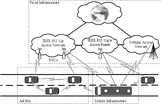
Figure 1 Vehicular Network Architecture
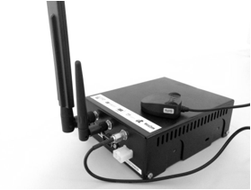
Figure 2 – On-Board Unit (OBU).
Each vehicle is equipped with an OBU with multiple wireless interfaces, which enable the vehicles to communicate both with other vehicles and with RSUs that are integrated in the infrastructure. OBUs and RSUs, illustrated in Figure 2, have a similar hardware, except for the antennas, which have higher gains in the RSUs. Figure 2.
The OBU includes the following elements:
- Single-Board Computer (SBC);
- Dedicated Short Range Communication (DSRC) wireless interface (IEEE 802.11p);
- WiFi interface (IEEE 802.11b/g/n);
- 4G Interface;
- GPS receiver;
- Antennas for each technology (round antenna is for WiFi and rectangular antenna is for IEEE 802.11p).
The OBUs are running a tailored Linux distribution based on Buildroot. The kernel was customized to include new features such as clock synchronization, as required by IEEE 802.11p. The driver was further extended to meet the requirements of IEEE 802.11p/WAVE. The RSUs have the same hardware as the OBUs, except for the cellular interface (which they do not require) and the Ethernet interface (required to connect to a switch from the fiber infrastructure).
Architecture
The automotive EVI environment available in IT-Av, Portugal, is represented in Figure 3. From the vehicular network perspective, it consists on several On-Board Units (OBUs), placed in vehicles, as well as Roadside Units (RSUs). An OBU can connect with other OBUs through IEEE 802.11p/WAVE links, and with RSUs via IEEE 802.11p/WAVE, IEEE 802.11g/WiFi or cellular links supported by the C-RAN concept working under the 4G/LTE specifications, frequency band 7.
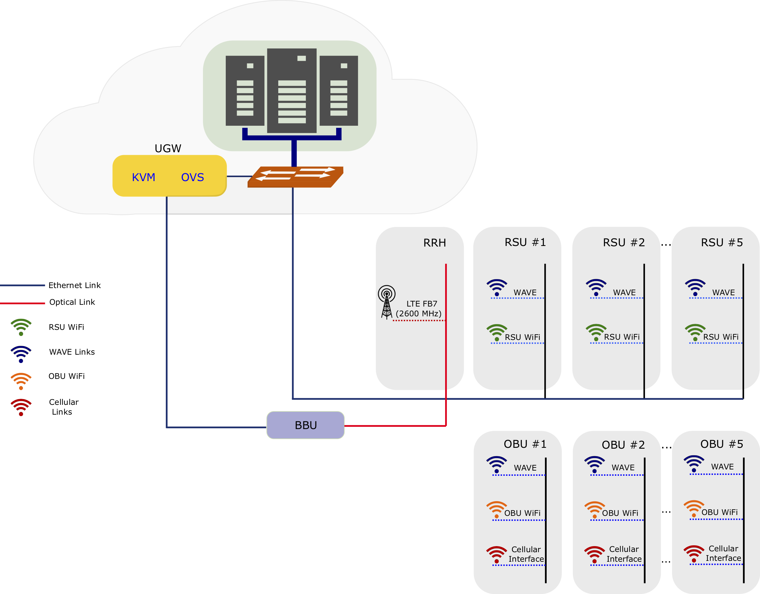
Figure 3 – IT-Av 5G automotive testbed infrastrucutre.
RSUs are connected to the IT-Av datacenter through Ethernet links. The C-RAN Remote Radio Head (RRH) is connected to the Base Band Unit (BBU) using optical fiber link, and from there to the Unifier Gateway (UGW) in charge to manage authentication, UEs sessions and end to end connectivity, which is available as a set of Virtual Network Functions (VNFs) deployed in the IT-Av infrastructure datacenter on an openstack instance. The IT-Av datacenter includes, among other components, the Virtualized Infrastructure Manager (VIM), directly connected to the multi-site orchestration managed by OSM MANO deployed in 5TONIC at UC3M, and the Network Function Virtualization Infrastructure (NFVI).
OBUs have access to the vehicular information such as velocity, GPS, and heading. This information can be used by the embedded in-Car Node Processor (in our case, a RaspberryPi) to take local decisions, but also be advertised to the other vehicles. Each vehicle has also access to information from the street and surroundings through embedded car video cameras and sensors (crossing roads and traffic lights, cars in the street, adverse conditions in the way, etc.) that will be transmitted using IEEE 802.11g/WiFi to the OBUs. Vehicles may use this information to support a variety of use cases, e.g., assisted driving, autonomous driving, collision avoidance, accident detection, emergency messages dissemination, On-Board Diagnosis (OBD) for car self-repairing (when integrated with the OBU), etc.. Figure 4 illustrates the IT-Av 5G automotive EVI architecture.
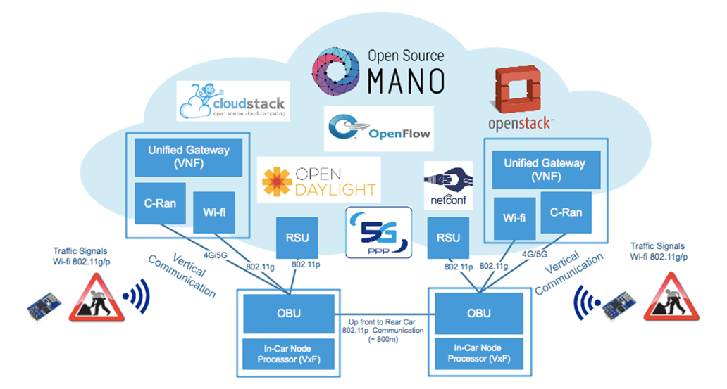
Figure 4 – IT-Av 5G automotive EVI architecture.
V2X communications may work directly between vehicles (IEEE 802.11p/WAVE) or using a cellular infrastructure (4G/5G) through a VNF Unified Gateway (provided by the b<>com partner). For the IT-Av automotive testbed both V2V and V2I are possible, enabling different experimentation forms.
Summarizing, the avaliable hardware for experimentation is the following:
- 10x RSUs/OBUs Single-Board Computer (SBC), Dedicated Short Range Communication (DSRC) wireless interface (IEEE 802.11p), WiFi interface (IEEE 802.11b/g/n), 4G Interface, GPS receiver, Antennas for each technology (round antenna is for WiFi and rectangular antenna is for IEEE 802.11p, and higher gains antennas in the RSUs);
- 5x ESP8266 devices to emulate the traffic signals through WiFi client and server based approach;
- 5x In-Car Node Processor: 3 ARM RaspberryPi V3 model B, RPi cameras for video streaming and 2x node processor x86 with 8 GB RAM and 8 core i7 processors;
- 1x small cell C-RAN using Band 7 (2.6GHz) for testing purposes (testing license is required “ANACOM/PT”), 2x Sim Cards 4G/LTE UICC Open Card for subscribers provisioning and 2x 4G dongles, 1x OAI EPC running on Xeon-based virtual machine (6 vCPU; RAM 10Gb; Disk 250GB).
5GinFIRE and IT-Av Testbed Datacenter
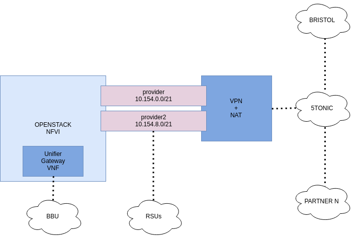
Figure 5 – IT-Av NFVI architecture.
Figure 5 shows the overall Network Function Virtualization Infrastructure (NFVI) deployed at IT-Av datacenter as part of 5GinFIRE multi-site orchestration.
The cloud environment of the IT-Av consists of an OpenStack Ocata instance that operates on top of Ubuntu 16.04 Server operating system. The controller node is available for the project at 10.154.0.10. This cloud environment has two networks: provider and provider2. The provider network is the management/control plane, which has the 10.154.0.0/21 subnet range. The provider2 netowrk is the data plane, which has the 10.154.8.0/21 subnet range.
The NFVI is composed by three compute nodes with the following resources:
- 72 vCPUs;
- 704 GB of memory;
- 2 TB of storage;
- NIC Passthrough, DPDK and SR-IOV capabilities;
- 1x 24-port 1Gbps switch, interconnecting the infrastructure.
Use Case: Assisted Driving with VNF Video Transcoder
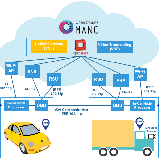
Figure 6 – 5GinFIRE assisted driving use case architecture.
To demonstrate the potential of the 5GinFIRE automotive testbed located in IT-Av, and to validate the workflow for new experimenters to deploy new VNFs, a VNF video transcoding camera-based car overtaking scenario was evaluated. In this scenario, illustrated in the Figure 6, each vehicle contains an OBU that provides the communication between vehicles and between each vehicle and the infrastructure. The OBU is also connected to an Android device, which can be a smartphone or a tablet, through WiFi, providing visual information for the driver. The vehicle contains a video camera on its front side. This information will be used by the driver to take decisions on driving, more specifically in overtaking situations. Regarding to the communication interfaces, each OBU is able to communicate with the infrastructure (RSUs) using the IEEE 802.11p/WAVE or IEEE 802.11g/WiFi, or using the 4G LTE cellular technology (C-RAN). The VNF video transcoding was available on site and deployed at the edge of the infrastructure.
Experimentation
Experimenters will have access to real OBUs, RSUs, In-Car Node Processors, ESP8266 devices and video cameras, having also the possibility to create and deploy their own VNFs from the 5GinFire portal within the IT-Av automotive testbed. Initially experimenters will have access to a controlled environment in the lab, with the possibility to evaluate and validate their own automotive VNFs services in terms of V2X communication performance and metrics (e.g., latency vs overhead, throughput vs packet loss, etc.), and test their own automotive VNFs within the car with its diversity of contextual-aware information gathered from extra sensors (traffic signals) and from OBUs internal sensors available (accelerometers, heading, speed, link quality connection, GPS, compass, RSSI, car neighbor’s density, etc.). In a later stage experiments will be performed through real experimentations in a controlled and outside environment.
Possible VNFs to be included and tested comprise Li-Fi communication between cars, car crash detection and emergency info dissemination, On-Board Diagnosis for self-repairing, collision avoidance (with machine learning techniques) and others.
Contact
Susana Sargento (susana@ua.pt) and Miguel Luís (nmal@av.it.pt)
Instituto de Telecomunicações, Aveiro, Portugal (IT-Av)
Campus Universitário de Santiago, 3810-193 AVEIRO – PORTUGAL